Burners
Supplemental firing systems have advanced quite a bit in recent years. Older burner designs had some inherent issues.
Gas turbine (GT) exhaust flow distribution and duct burner fuel gas flow distribution are critically important in duct burner design and operation. Good flow distribution is required to minimize emissions, ensure flame stability, minimize flame length and to protect against flame impingement on side wall liners and other components. Exhaust and Fuel gas distribution can have a significant effect on the temperature variation after the burner. Large temperature variations can result in locally overheated superheater and reheater components. Nooter/Eriksen can perform an engineering study to evaluate the HRSG design and components in order to determine that the maximum amount of efficiency is achieved.
Older burner designs have nothing to prevent backflow from the HRSG into the burner feed lines. When the burner is not in use, exhaust gas backflows from the HRSG into the gas feed lines. The hot exhaust cools in the feed lines, and the H2O condenses out. Over time, water accumulates in the feed piping. The next time the burner is operated, a slug of water is force through the piping and exits at the lowest burner element. When the cool water hits the hot burner element, the element is quenched which can cause severe bowing of the element. On newer designs, control valves have been added to each burner element. These valves are programmed to automatically close when the burner is not in use.
Older burner element designs also have spray orifices that were all drilled to the same diameter. The issue with this approach is that this creates an uneven flow distribution which leads to uneven flame lengths. When flames become too long, they impinge surrounding liner, vibration supports, and tubes. Impinged material glows orange hot and when it cools, it buckles and bows. New burner elements have variable diameter holes specified to create uniform flame length. Nooter/Eriksen can provide recommendations to drill out specific holes to enlarged diameters and pin other holes closed.
When it comes to replacing or modifying aging or deficient burner elements, Nooter/Eriksen has the expertise to perform engineering studies to evaluate the HRSG design and components in order to determine the maximum amount of efficiency and reliability is achieved. By partnering with Nooter/Eriksen in this effort, your plant can go from a simple replacement in-kind, to achieving an overall burner package upgrade that will provide the best long term and reliable system for your HRSG’s specific needs.
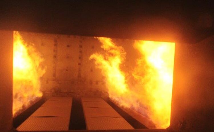
Observation Port View
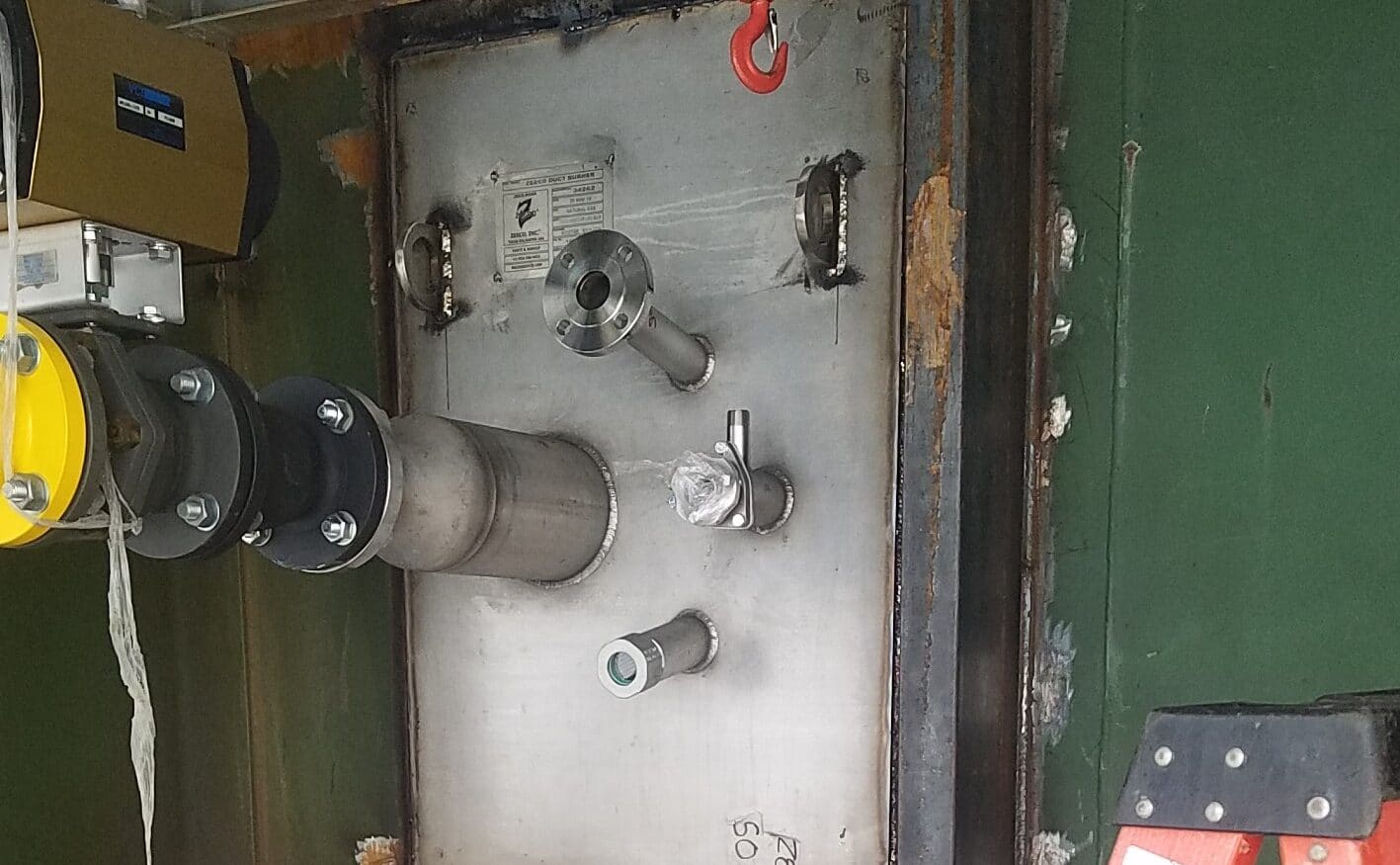
Burner Install
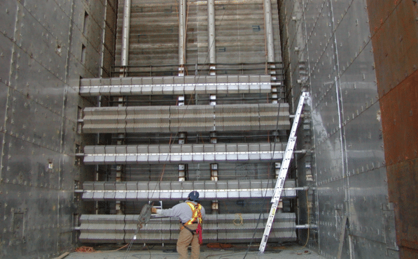
Runners and Baffles install
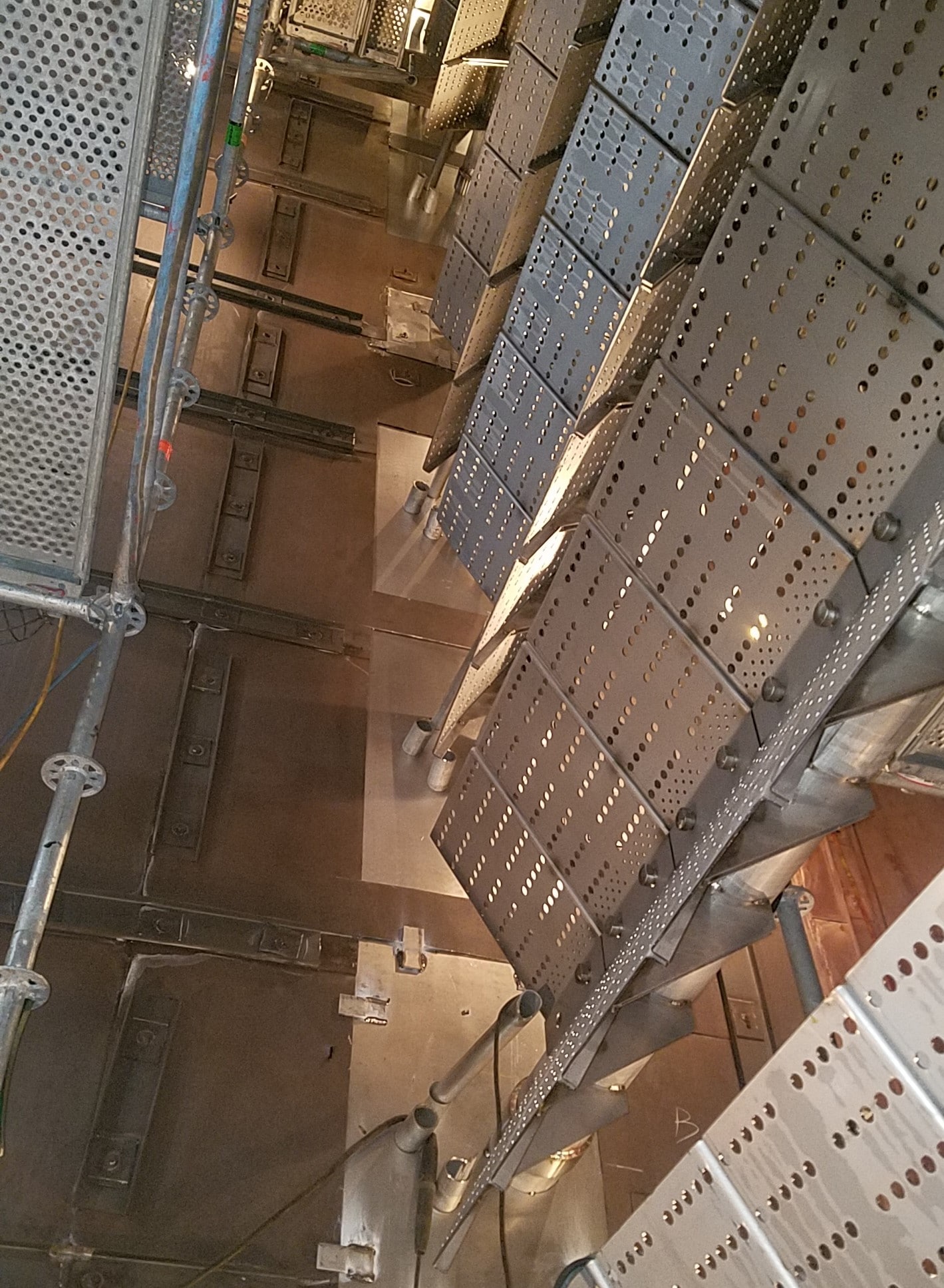
Burner Runners